
From PD Detection to Maintenance Action: 24/7 Monitoring and Accurate Localization for Critical Generator Step-Up Transformers

Screenshot 2026-09-30 120416

For a power plant, the generator step-up transformer (GSU) is a critical link between generation and the grid. When partial discharge (PD) is detected, the real challenge for asset managers is not simply confirming that activity exists – it is deciding what to do next.

Is the PD persistent or intermittent? Where is the source? Is it stable or increasing? How does it behave under actual loading and operating conditions? Can intervention wait until the next planned outage, or is earlier action needed?

This article explores how 24/7 fibre-optic acoustic monitoring, accurate PD localization and long-term trending can help answer these practical questions – turning a PD indication into actionable information for condition assessment, risk-informed maintenance planning, and GSU availability.

Why locating the PD source is critical for maintenance planning?

On a critical GSU, detecting PD is not enough to prepare the next outage. Operations and maintenance (O&M) teams still need to know whether the activity is associated with a winding, lead, bushing region or another insulation structure, and which area must be accessed. Without a reliable location, the inspection scope, required specialists, spare parts and expected repair time may remain uncertain until the unit is already offline.

Dissolved gas analysis (DGA), electrical PD measurements and periodic testing provide important evidence, but they do not necessarily identify the physical source. Repeatable acoustic localization narrows the investigation to a defined area, helping the team prepare a focused work package and use limited GSU outage time more effectively.

How a credible acoustic result is built?

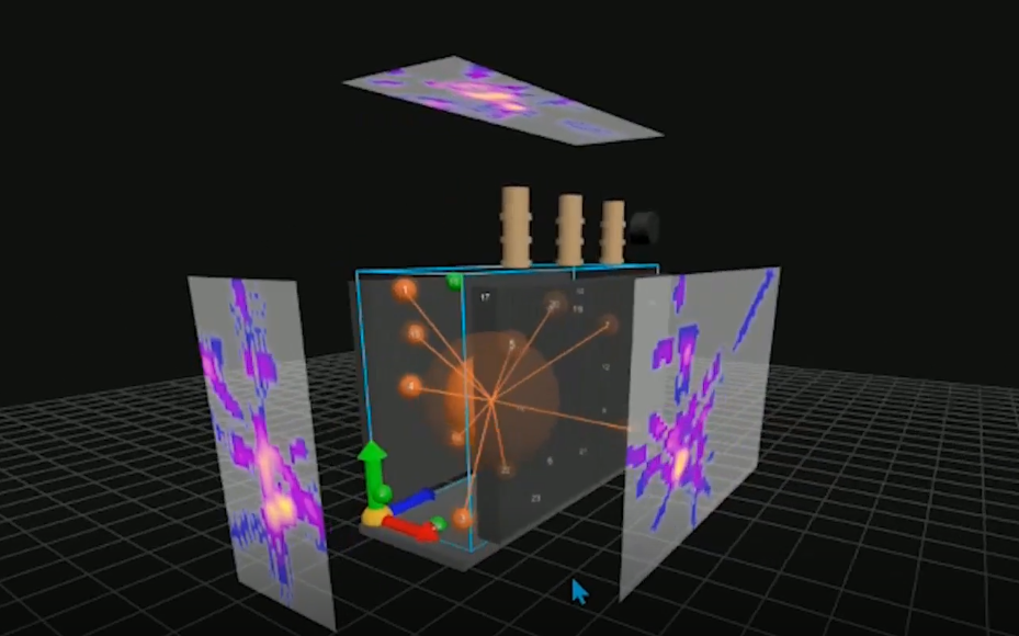
The OptiFinder Monitoring Platform uses a network of up to 32 externally mounted fibre-optic acoustic sensors for continuous online PD detection, phase-resolved partial discharge (PRPD) analysis, long-term trending and 2D/3D PD source localization. 3D localization pinpoints the physical source within the transformer volume, to within 15 cm accuracy under validated conditions. The 2D overlay presents a heatmap of PD activity projected onto the transformer surface.

Confidence in the acoustic result comes from a combination of indicators:

1. Phase relationship and filtering

A repeatable PRPD pattern is correlated with the alternating current (AC) voltage phase, while vibration filtering and noise rejection distinguish PD-related activity from background noise.

2. Multi-sensor correlation

The same event is detected across several sensors, and relative arrival times are used for time-difference-of-arrival localization.

3. Repeatable location

Recurring events that continue to localize to the same region provide stronger evidence of an internal source than a single event.

4. Persistence and trend

Repeated phase-related activity under actual load, temperature and switching conditions helps show whether the activity is stable, intermittent or increasing over time.

5. Diagnostic correlation

Where relevant, Optics11’s experts can compare OptiFinder Monitoring Platform results with DGA, electrical PD, ultra-high frequency (UHF) and operating data to build a more complete picture of transformer condition.

The output is not another standalone alarm. It is an evidence set: phase-related behaviour, multi-sensor detection, a consistent physical location and a trend over time.

The OptiFinder Monitoring Platform operates using optical signals and is intrinsically immune to electromagnetic interference (EMI), making the sensing principle particularly suitable for the challenging
electromagnetic environment of power transformers and GSUs. Its externally mounted, non-intrusive sensor network can be integrated without modification of the transformer’s insulation system. While conventional electrical PD measurements provide valuable information for detecting and characterising PD activity, acoustic emission (AE), as a non-conventional PD detection method, adds spatial information, enabling the source of detected activity to be accurately localised inside the transformer.

Why GSUs need continuous condition awareness?

GSUs operate under the duty cycle of the generating unit. CIGRE TB 939 identifies GSUs as having a higher failure rate than substation transformers across most voltage classes, with sustained high loading highlighted as one contributing factor. Baseload GSUs can run for long periods at high load; peaking, hydro-regulating and pumped-storage units may see more cycling and operating transitions. Continuous monitoring tracks PD under actual operating conditions, including activity that may be missed by a periodic snapshot.

For O&M teams, the value is lead time. GSU work is normally coordinated with turbine, generator and other major plant maintenance. Early detection of abnormal or increasing PD creates time to trend the activity, run complementary diagnostics, localise the probable source, procure spares, mobilise specialists and bring
transformer work into the next planned outage. The key question becomes: does the combined evidence support continued operation to the planned outage, increased surveillance, complementary diagnostics, or accelerated intervention?

The following transmission-transformer case illustrates the same diagnostic workflow that can be applied to critical GSUs. In one documented utility case, two 380/150/50 kV transformers were monitored for more than two months: one was already considered PD suspect, while the other was treated as the comparison transformer. Significant PD activity was detected in both. The reference transformer was then selected for a dedicated follow-up campaign using 32 sensors, which again localised the PD source, and subsequent DGA also indicated abnormal PD-related behaviour.

The maintenance lesson is not that DGA failed, but that the methods answer different questions. DGA shows the chemical consequences of faults; continuous PD monitoring provides direct information on PD activity, its physical location and how it evolves over time.

Used together, they can change which transformer receives attention and whether the next step is continued surveillance, complementary diagnostics or a prepared intervention.

What the program must deliver?

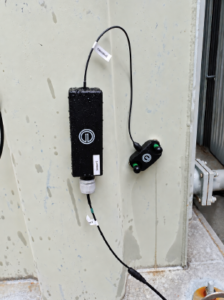
Reliable measurement starts with sensor placement and good acoustic coupling. External sensors can be retrofitted while energised – useful for critical GSUs where a dedicated installation outage is hard to justify. Safe access may limit preferred positions; a planned outage can later optimise placement where needed.


Five questions for the work space:

  1. Is phase-related PD present?
  2. Does it repeat and  localise separately from noise?
  3. Where is the source?
  4. Is activity stable or deteriorating under real GS conditions?
  5. Can this GSU remain in service to the planned outage or should action be accelerated?

Where to start?

Prioritise by GSU risk, not age alone. Strong candidates have limited redundancy, high or cyclic loading, difficult outage scheduling, long replacement lead times, severe generation consequences if unavailable, or a developing issue already indicated by DGA, an electrical PD measurement or a spot test – while its location and trend remain unclear.

The goal is to give O&M teams enough evidence to make the next decision with confidence. By combining continuous PD detection, repeatable localization and trending over time, the OptiFinder Monitoring Platform helps teams build a clearer picture of what is developing inside the transformer – and supports the decision to continue operating, increase monitoring or prepare an intervention based on how the activity is behaving and where it is located.

Dr. Hamed Hashemi-DezakiDr. Hamed Hashemi-Dezaki

PRINCIPAL PARTIAL DISCHARGE ENGINEER

Qualification note: Localization accuracy of up to 15 cm applies under validated deployment conditions. The OptiFinder Monitoring Platform provides acoustic PD detection and localization; it is not an IEC 60270 electrical partial discharge measurement instrument. OptiFinder products are currently marketed publicly
under the name “OptiFender.”

Technical basis: CIGRE TB 939 – transformer reliability and failure statistics; CIGRE TB 761 – condition assessment of power transformers; CIGRE TB 962 – transformer maintenance; IEEE C57.127 – acoustic-emission principles; IEC 60076-3 – insulation levels and dielectric tests.

Access Our Defense Downloads.

Insights

Energy

The Transformer Decision Gap: When to Keep Operating, Monitor or Intervene

Energy

From PD Detection to Maintenance Action: 24/7 Monitoring and Accurate Localization for Critical Generator Step-Up Transformers

Energy

Optics11 deploys purpose-built fiber-optic sensors for Europe’s largest fusion reactor

Energy

OptiFender becomes OptiFinder: the next chapter in fiber-optic Partial Discharge monitoring

Press releases

Dutch Ministry of Defence selects OPTICS11 to develop and deliver new “anti-submarine warfare in a box” capability.

Energy

OptiFinder software update delivers an improved 3D localization experience

Underwater Security

OptiBarrier Opens Its First Offshore Test Center in Rostock, Germany

Energy

Optics11 appoints Derk te Bokkel as President of the Supervisory Board